RTO (Regenerative Thermal Oxidizer)
Product Introduction
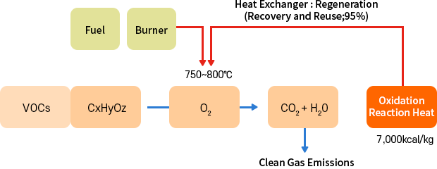
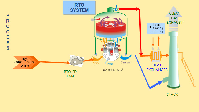
- RTO (Regenerative Thermal Oxidizer) is a device that combusts Volatile Organic Compounds (VOCs) at high temperatures of 800°C, achieving over 99% removal efficiency.
- It utilizes ceramic heat exchangers to recover more than 95% of the heat generated during the combustion of VOCs, thereby minimizing the consumption of auxiliary fuels.
Operating parameters for 99% Destruction
- Temperature : 750 ~ 850 ℃ ( 300 ~ 350 ℃. With Catalyst)
- Residence time : 0.5 ~ 1 sec
- Turbulence : Re > 10,000
- O2 Concentration: Above 12% at 800℃
Characteristics
- Very high removal efficiency for volatile organic compounds (over 98%).
- Low operating costs due to heat recovery, with a thermal recovery(over 95%)
- Capable of operation without auxiliary fuel when the organic compound concentration is 1.5~2g/Nm³.
- Reducing fuel costs by utilizing waste heat for heating due to high incoming concentrations.
- No pressure fluctuations (inlet suction) during long-term operation.
- Long durability with minimal breakdowns.
- Compact design compared to activated carbon adsorption systems.
- Low secondary air pollution factors (minimal NOx emissions)
Application Areas
- 1Printing and Plating Industry
- 2Plating and Surface Treatment
- 3Petrochemical Industry
- 4Facilities Using Organic Solvents
Disadvantages
- Initial installation costs are higher compared to adsorption towers.
- Low incoming concentrations can result in higher fuel costs.
배출농도에 따른 최적 VOCs 처리시스템
| 입구 THC 농도(ppm) |
처리 방법 |
상세설명 |
| ~ 35 ~ |
흡착 교환법 |
흡착제를 이용하여 흡착 후 포화되면 새 것으로 교체함 |
| 흡착 재생법 |
흡착 후 포화되면 열, 압력 등을 이용하여 흡착제를 재생 |
| ~ 350 ~ |
농축기 |
+ |
직접 소각법 |
농축기로부터 농축, 탈착된 성분을 직접 소각함 |
| 축열 소각법(RTO) |
농축기로부터 농축, 탈착된 성분을 축열식 소각기로 소각함 |
| 촉매 소각법(RCO) |
농축기로부터 농축, 탈착된 성분을 촉매식 소각기로 소각함 |
| ~ 3,500 ~ |
직접 소각법 (TO) |
유입되는 성분을 직접 소각함 |
| 축열 소각법(RTO) |
유입되는 성분을 축열식 소각기로 소각함 |
| 촉매 소각법(RCO) |
유입되는 성분을 촉매식 소각기로 소각함 |
| ~ 35,000 |
희석 소각법 |
유입되는 성분을 폭발하한 농도로 희석하여 직접 소각함 |
| 농축 회수법 |
유입되는 성분을 흡착, 탈착(농축)한 후 냉각, 응축하여 회수함 |
| > 35,000 |
응축 회수법 |
유입되는 성분을 냉각, 응축하여 회수함 |
VOC 처리시설의 특징 및 장단점
| 구분 |
특징 및 장점 |
단점 |
적용공정 |
| 직연식연소로 (TO) |
- 가스를 700~900℃에서 산화분해
- 완전연소시 고효율(99%)가능
- 타르, 분진의 허용성 높음
- 낮은 초기투자비용
|
- 불연성용제 적용 불가
- 연소시 2차 공해발생 주의
- 높은 운전비 (고온연소,보조연료多)
- 열교환기 이용
- 고온연소에따른 설비대형화
|
- 풍량변화가 없는 공정 저/중풍량
- 고농도 (LEL20~25%)
|
| 촉매산화장치 (CO) |
- 열교환기와 촉매를 이용
- 가스를 300~450℃에서 산화분해
- 낮은 운전비 (저온연소)
- 저온연소에따른 COMPACT한설비
- 전기열원 사용가능
|
- 유기실리콘등 촉매독 주의필요
- 주기적 촉매재생 필요
|
- 촉매독없는 중/대풍량(1000CMM 이하)
- 중간 농도 (LEL10~20%)
|
| 축열식연소로 (RTO) |
- 가스를 800~850℃에서 산화분해
- 축열체에서 95%이상의 열회수
- 열회수율 높아 운전비 저렴
- 2차 공해요인이 적음
|
- 불연성용제 적용 불가
- 높은 초기투자비
- 심한 풍량/농도변화에 적응곤란
|
- 중풍량 ( 100CMM 이상)
- 중간농도 (LEL10%)
|
| 축열촉매연소 (RCO) |
- 가스를 250~400℃에서 산화분해
- 축열체에서 92%이상의 열회수
- 열회수율 높아 운전비 저렴
- 2차 공해요인이 적음
|
- 유기실리콘등 촉매독 주의필요
- 주기적 촉매재생 필요
- 높은 초기투자비
- 심한 풍량/농도변화에 적응곤란
|
- 비교적 대풍량 (300CMM 이상)
- 낮은 농도 (LEL4%)
|
| 흡착(농축) (ROTOR) |
- 풍량, 농도변화에 대응용이
- 불연성, 가연성 모두 처리가능
- 운전비 저렴
- 타르, 분진의 허용성 높음
|
- 폭발하한의 1/3~1/4이상 농축불가
- 고비점물질, 분진, MIST등이 포함시 전처리필요
- 흡착제 주기적 재생/교체 필요
- 농축가스의 2차처리 필요 (산화/회수)
|
|
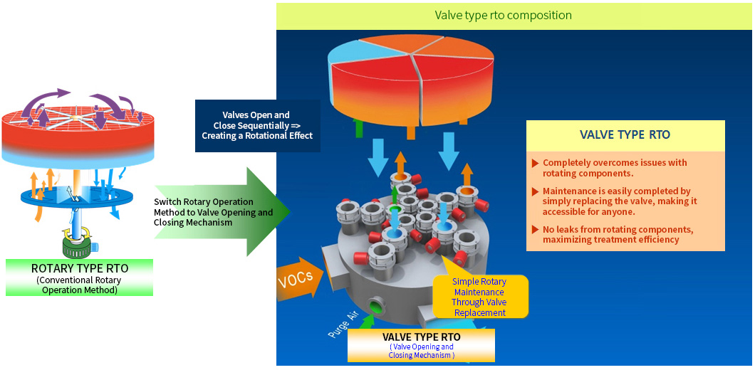
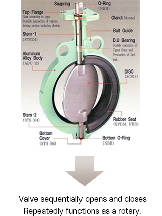
Feature of VALVE-RTO
- The rotary rotation method experiences a significant drop in treatment efficiency in the event of a leak and is difficult to maintain; therefore, ACE applies a valve opening and closing method.
Comparison of DISK Rotary TYPE vs. VALVE TYPE
| Category |
DISK Rotation TYPE |
VALVE TYPE |
| Advantages |
- Relatively simple structure.
- Constructed with cast materials to ensure durability.
- Slightly lower cost.
- Usable at 150~200℃ high temperatures.
|
- No leaks at all.
- High treatment efficiency.
- Usable above 250℃
- imple maintenance (easy for anyone to repair).
- Minimal pressure loss.
- Valve usage is semi-permanent.
|
| Disadvantages |
- Requires replacement if wear-related failure occurs.
- Treatment efficiency decreases with prolonged use due to wear.
- The rotary is integrated and cannot be repaired outside the manufacturer, requiring a significant amount of time for maintenance.
- Difficult sealing due to cast structure, leading to leaks.
- High pressure loss in rotary.
|
- Control systems are somewhat complex.
- Higher cost.
- Periodic maintenance of actuator solenoid required
|
| Maintenance Cycle |
- 1 year (packing within 6 months)
|
- Actuator guaranteed for 2 years.
|
| Treatment Efficiency |
|
|
- Combustion Chamber Temp. (750℃~800℃)
PERFECT – Advantage of RTO
- Excellent VOC removal efficiency(99~99.5%).
- Sustainable processing efficiency rate
- Robust design for temp. change and rotary sealing
- Easy rotary self-maintenance
- Operating even with some of valve malfunction
- Controllable rotary size depending on air flow, operating with large air flow as well
- Easy to operate & maintain
- Good heat recovery rate due to large air distribution range
- Power cost saving due to low pressure loss
- Low cost for maintenance
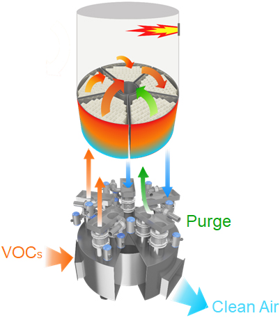
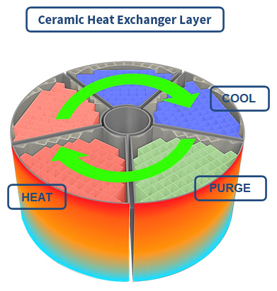
RTO [VALVE ROTARY SYSTEM]
- Combustion chamber, Floor structure & Distribution chamber are divided into fan-shaped 5 cells.
- They perform pre-heating and heat-recovering for each sequentially changing 2 BED of cool or heat zone with rotary rotation.
- For this moment, there is purge zone b/t cool & heat zone to prevent mixing raw gad and treated gas by holding raw gas
- while transferring from cooling to heating.
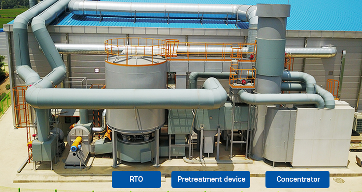
VOCs combustion treatment process
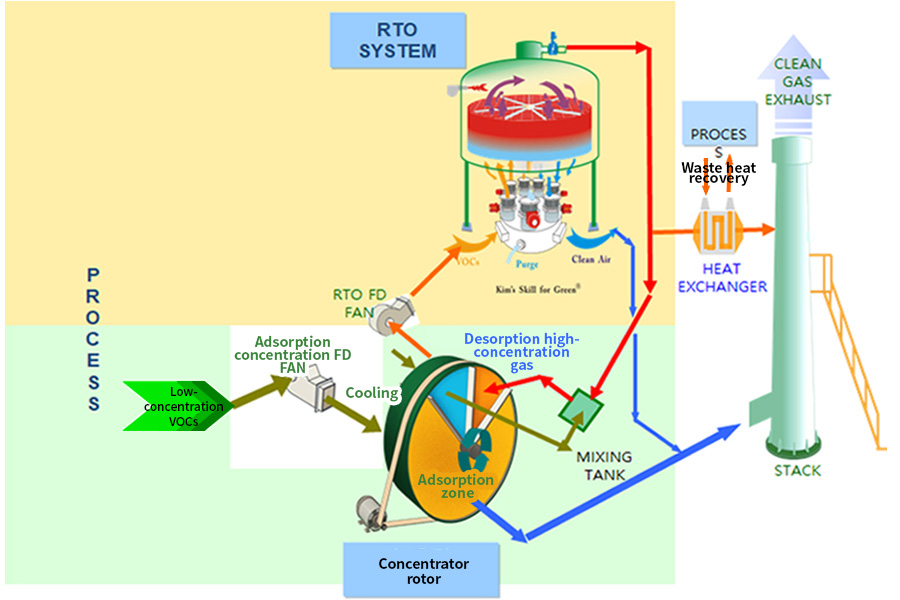
Concentration+RTO
Concentration + RTO
- Low-concentration, high-flow VOC-containing air is concentrated by a concentrator into high-concentration, low-flow air before oxidation in a combustion device.
- The concentration process reduces the size of the combustion device, allowing for a cost-effective and compact solution.
- The concentration process reduces fuel consumption of the combustion device, utilizing the regeneration heat source from the combustion exhaust.
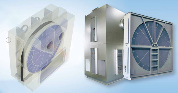
CONCENTRATOR
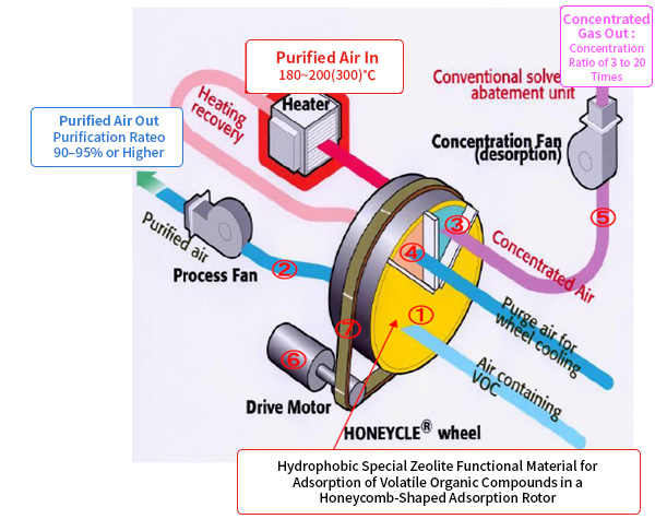
- The concentrator is a device that processes low-concentration, high-flow VOC-containing gases into high-concentration, low-flow gases for exhaust treatment, efficiently handling VOCs in combination with an RTO.
- Concentrated zeolite is a porous material with micro-pores (0.2–1.0 nm) that generates molecular vibrations to facilitate adsorption within these micro-pores.
- The adsorption characteristics can vary significantly depending on the type of zeolite.
Operational Description of the Concentrator
- 1VOCs are introduced and adsorbed as they pass through the adsorption rotor, designed for an adsorption efficiency of 90–95%.
- 2Other clean air is discharged through the stack.
- 3The VOCs adsorbed on the rotor are separated and desorbed by hot air in the high-temperature zone (180°C–200°C) as the rotor rotates.
- 4The heated area is then regenerated to restore its adsorption capacity.
- 5The desorbed high-concentration gas is combusted in the RTO, achieving a concentration 3 to 20 times greater than the incoming VOC concentration.
- 6The rotor continuously processes the cycle of adsorption, desorption, cooling, and re-adsorption at a constant speed driven by the motor.
- 7The motor and rotor are connected through a driving chain.
Characteristics
- 1The rotary design is simple, making maintenance convenient.
- 2Continuous concentration processing of VOCs is possible.
- 3Suitable for handling low-concentration, high-flow volumes, reducing running costs.
- 4The rotor uses hydrophobic zeolite as the adsorbent, which is non-combustible.
- 5Capable of processing a wide variety of solvents (VOCs).
- 6Concentration of VOCs can be increased by 3 to 20 times.
Application Examples
- Painting Booths
- Local Exhaust in Printing Lines
- Exhaust in Coating Zones
Typical VOC Application Table 1
Performance Ratings: A: Excellent, B: Good, C: Possible, D: Not Applicable
|
VOC |
ROTOR LINEUP |
| HZ-AM |
HZ-BM |
HZ-XM |
| Aromatic compounds |
Toluene |
B |
A |
B |
| Xylene |
A |
C |
A |
| Trimethyle benzene |
A |
D |
A |
| Styrene |
D |
A |
D |
| Ketones |
Acetone |
C |
B |
B |
| MEK |
B |
A |
A |
| MIBK |
B |
A |
A |
| Cyclohexanone |
A |
C |
A |
| Esters |
Ethyl Acetate |
B |
A |
A |
| Butyl Acetate |
B |
A |
A |
| PGMEA |
B |
A |
A |
| Alcohols |
Methanol |
C |
C |
C |
| Ethanol |
C |
B |
C |
| IPA |
C |
B |
B |
| Butanl |
B |
A |
A |
| others |
Naphtha |
A~D |
A~D |
A~D |
| NMP |
A |
C |
B |
| DCM |
D |
B |
C |
Typical VOC Application Table 2
| GROUP |
NAME |
VOC CONCENTRATION ROTOR |
| V-MAX |
| Ⅰ |
Ⅱ |
Ⅲ |
Ⅴ |
| Alphatic hydrocarbons |
n-Hexane |
○ |
○ |
◎ |
◎ |
| Cyclohexane |
△ |
△ |
△ |
△ |
| Alcohols |
Methanol |
× |
× |
△ |
○ |
| Ethanol |
△ |
○ |
△ |
◎ |
| n-Propanol |
○ |
○ |
○ |
◎ |
| Isopropanol (IPA) |
○ |
○ |
○ |
◎ |
| n-Butanol |
◎ |
◎ |
◎ |
◎ |
| Diacetone alcohol |
◎ |
◎ |
◎ |
◎ |
| Ketones |
Acetone |
△ |
△ |
○ |
◎ |
| Diacetone alcohol |
○ |
◎ |
◎ |
◎ |
| Methyl ethyl ketone (MEK) |
◎ |
◎ |
◎ |
◎ |
| Methyl isobutyl ketone (MIBK) |
◎ |
◎ |
◎ |
◎ |
| Methyl amyl ketone (MAK) |
◎ |
◎ |
◎ |
◎ |
| Methyl propyl ketone |
◎ |
◎ |
◎ |
◎ |
| Cyclohexanone |
◎ |
◎ |
△ |
△ |
| Esters |
Ethyl acetate |
○ |
○ |
◎ |
◎ |
| n-Propyl acetate |
○ |
◎ |
◎ |
◎ |
| n-Butyl acetate |
◎ |
◎ |
◎ |
◎ |
| Methyl cellosolve acetate |
◎ |
◎ |
○ |
○ |
| Ethyl cellosolve acetate |
◎ |
◎ |
○ |
○ |
| Butyl cellosolve acetate |
◎ |
◎ |
○ |
○ |
| Propylene glycol monomethyl ether acetate (PGMEA) |
◎ |
◎ |
○ |
○ |
| Ethers |
Methyl cellosolve |
◎ |
◎ |
◎ |
◎ |
| Cellosolve |
◎ |
◎ |
○ |
○ |
| Butyl cellosolve |
◎ |
◎ |
○ |
○ |
| Propylene glycol methyl ether (PGME) |
◎ |
◎ |
◎ |
◎ |
| Aromatic hydrocarbons |
Benzene |
△ |
△ |
○ |
○ |
| Toluene |
○ |
○ |
○ |
○ |
| o-Xylene |
◎ |
◎ |
× |
× |
| m-Xylene |
◎ |
◎ |
× |
× |
| p-Xylene |
◎ |
◎ |
○ |
○ |
| Styrene |
× |
× |
◎ |
◎ |
| Ethyl benzene |
◎ |
◎ |
○ |
○ |
| Chlorinatec hydrocarbons |
Dichloro methane |
× |
△ |
○ |
○ |
| Trichloro ethane |
△ |
△ |
○ |
○ |
| Others |
N-methyl-2-pyrrolidone (NMP) |
◎ |
◎ |
○ |
◎ |
| N,N-dimethylformamide (DMF) |
○ |
◎ |
◎ |
◎ |
| N,N-dimethylacetamide (DMAC) |
◎ |
◎ |
○ |
○ |
| Dimethylcarbonate (DMC) |
○ |
◎ |
◎ |
◎ |
| Tetrahydrofuran (THF) |
○ |
○ |
◎ |
◎ |
Example of Valve Rotary replacement
< RTO 18,000 + Concentrator 90,000 m3/hr >
Design Elements of the RTO System
| Review Items |
Details |
Design Approach |
| Inlet THC Concentration Variation |
High Concentration Inlet |
Risk of explosion if LEL concentration is exceeded. |
Concentration balancing using adsorbents (zeolite) (prevent explosions and reduce fuel costs) |
| Low Concentration Inlet |
Excess fuel gas consumption due to lack of thermal energy |
| Risk of explosion and fire |
THC Concentration Management |
If the THC concentration exceeds the LEL concentration, it poses a risk of explosion and fire |
- Monitoring combustible gas concentrations with IR temperature sensors and THC sensors
- Maintain the LEL concentration below 25% at 25°C
- In the case of high concentration inflow, introduce fresh air and execute shutdown (emergency vent) if control is lost after an alarm
- Control combustion chamber temperature during high concentration inflow (Hot Bypass, Cool Bypass System)
- After re-start, purge with outside air before igniting the burner
|
| Device Protection |
Even in the event of an explosion, pressure, backfire, and other phenomena are suppressed to protect related devices |
- Install explosion relief vents or rupture disks where necessary
- Prevent system backfire using a wet scrubber (flame arrester)
|
| Clogging Issues |
- Clogging from incoming dust, mist, and tar
- Manual cleaning
- Replace Adsorbent
|
- Removal of fine particulate matter using fine filters
- Removal of particulate matter through cooling, condensation, and inertial collision using a wet scrubber
- Apply bottom-layer adsorbent separation for easy maintenance
- Execute bake-out sequence after shutdown to eliminate smoke and odor
- Implement high-temperature positive pressure purge system and pre-heating for continuous operation to prevent adsorbent blockage
- Protect upper adsorbent from damage (control burner step during heating, proportional control of hot bypass)
|
| Performance Guarantee |
Fuel Consumption |
- Emergency discharge to prevent overheating during high concentrations
- Excessive fuel gas usage due to thermal energy shortage during low concentrations
|
- Fuel consumption varies based on inlet concentration and thermal efficiency
- Concentration balancing by the adsorbent layer reduces fuel consumption
|
| Thermal Efficiency |
Guaranteed above 95% unless specified by the customer |
- Reinforcement of insulation and adsorbent
- Guarantees above 97% if requested by the customer
- Application of separated rotary to prevent uneven flow
|
| THC Treatment Efficiency |
Guaranteed above 99% unless specified by the customer |
- Increase in combustion chamber volume and temperature
- Application of high-temperature positive pressure purge system and pre-heating
- RTO reprocessing system
|